


DESCRIPTION
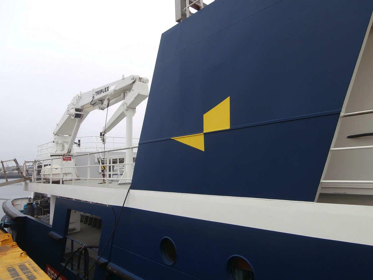
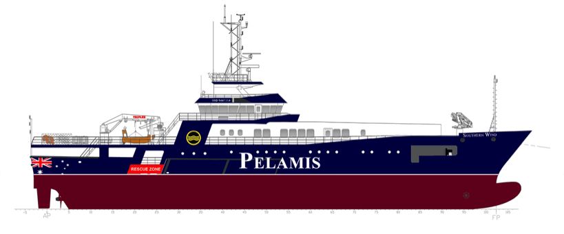
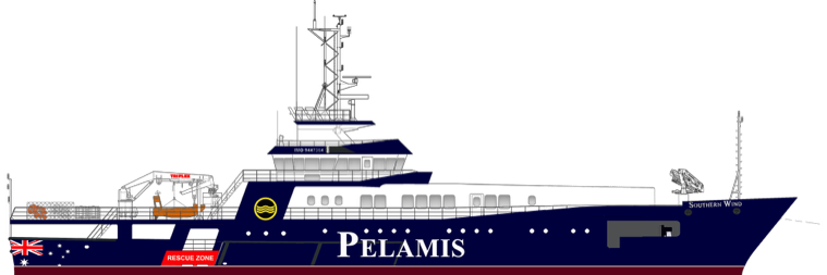
The Fishing Vessel Southern Wind is the first in the new Pelamis Long-line Tuna fishing fleet. Built in the Cardama Shipyard in Vigo Spain, the 69-metre vessel, represents the latest in Diesel-electric propulsion and Ultra-Low Temperature freezing technology. Designed for Australia's Southern Ocean, she is well suited for catching and processing Southern Bluefin Tuna for the premium Japanese market. Arriving Australia in October 2023.
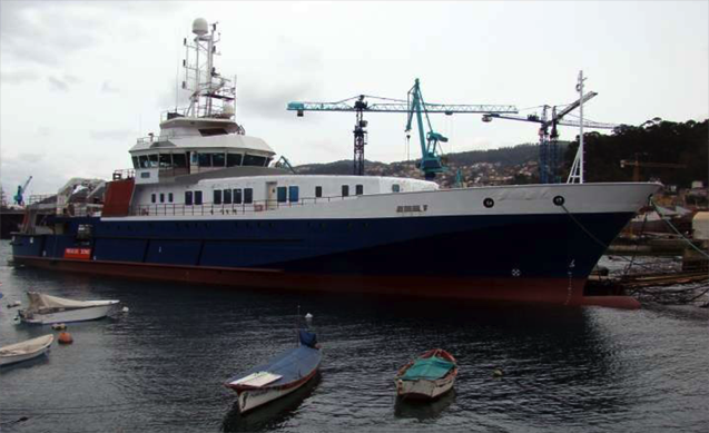
The vessel was built as a Fisheries Protection vessel, equipped with the most advanced diesel-electric technology, but was never commissioned and remained unused until Pelamis, in co-operation with the Cardama Shipyard undertook the conversion of the vessel to a Tuna Long-liner.
PARTICULARS
Length Overall:
Length between PP:
Beam Moulded:
Max. Draught:
Fuel:
Service Speed
Max. Speed on sea trials
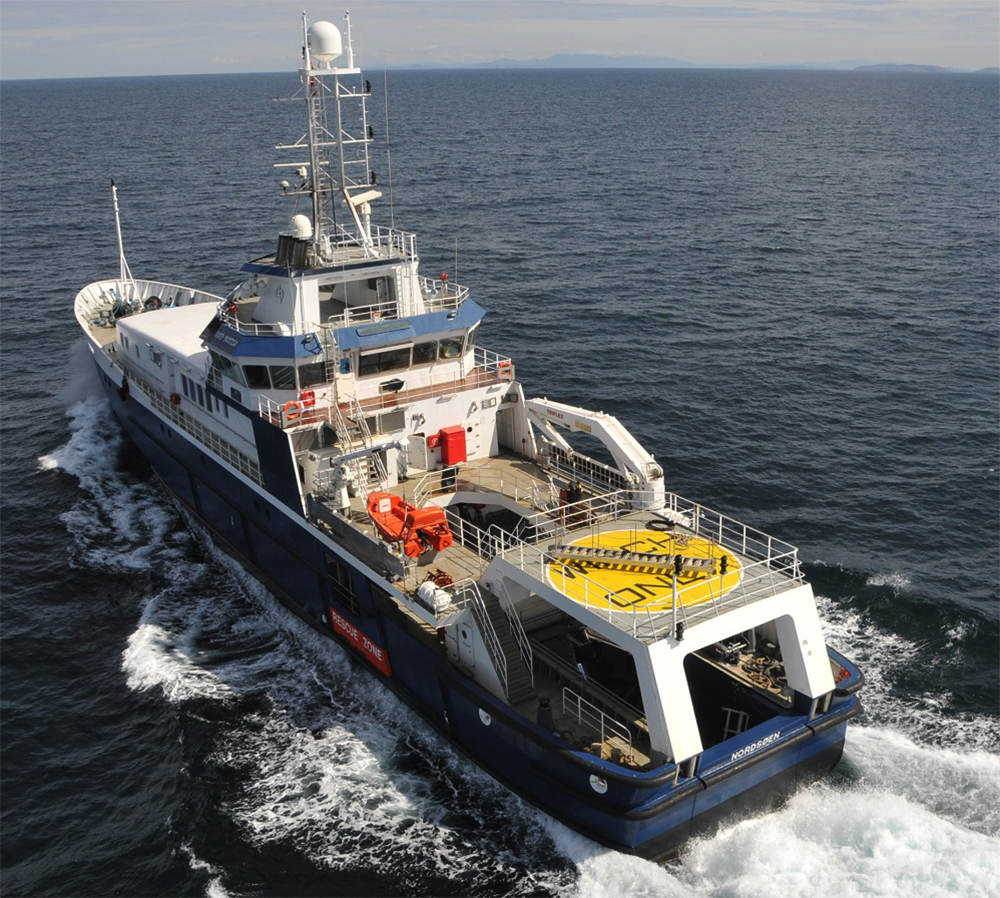
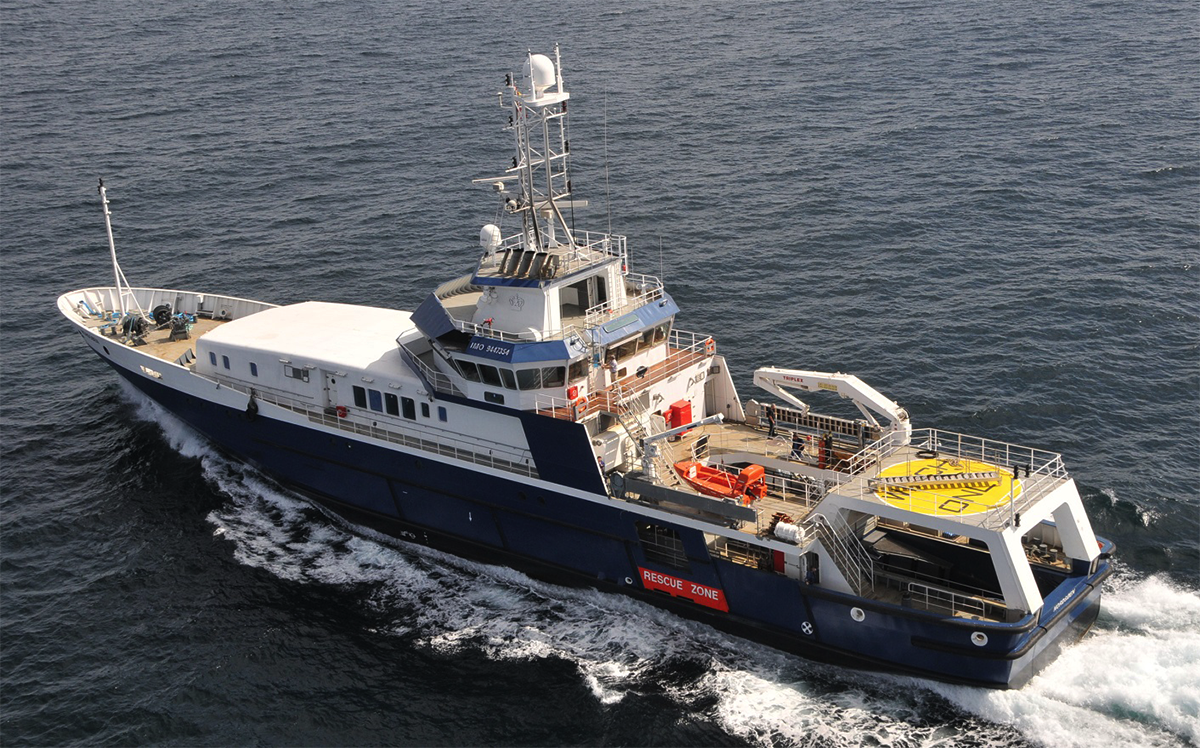
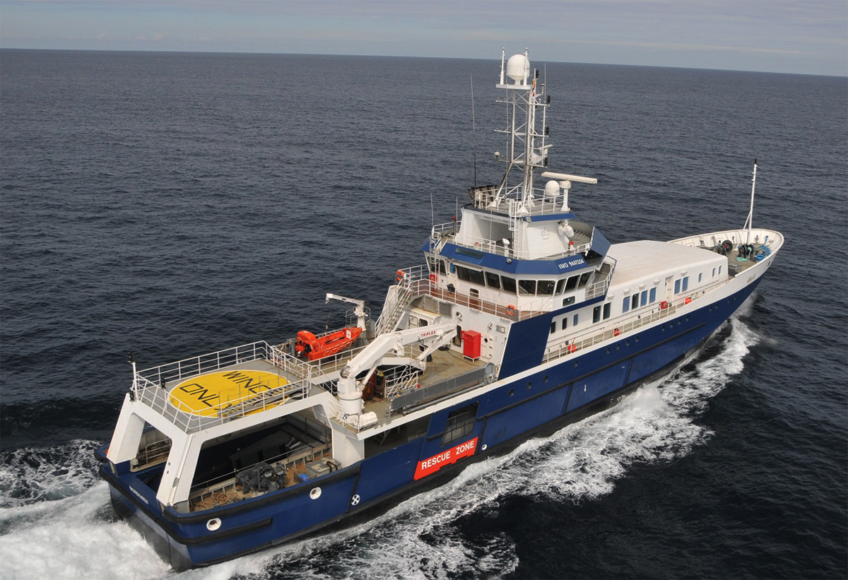
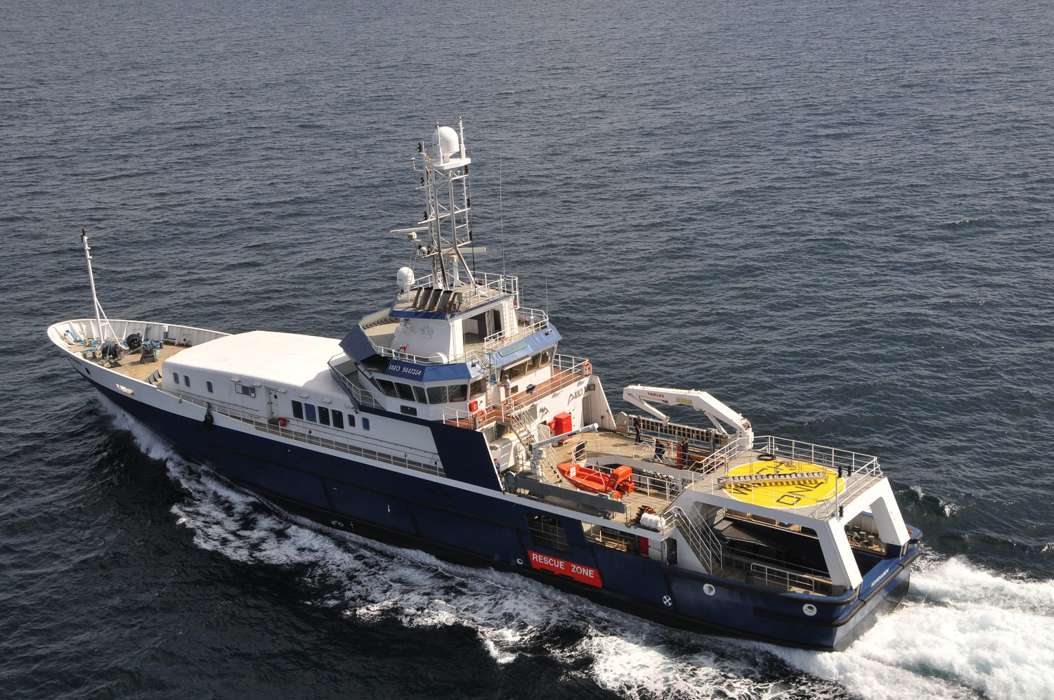
PATROL FISHERY AND RESCUE VESSEL TO TUNA LONG-LINER
The main hull and the superstructure up to and including deck 4 are constructed of mild steel according to drawings worked out by KEH and approved by Class and Owner. The deckhouse on deck 4, the bridge, the funnel and the antenna platform, as well as the elevated deck above the boarding boat recess have been made of aluminium alloy.
The starting point for this project is the above mentioned vessel (C-242), originally built as “ocean going fisheries patrol and rescue vessel” for the North Sea, which hasn’t entered in service and is laid-up at Cardama’s.
The vessel was built, classed and tested under the special survey of Det Norske Veritas (merged now as DNVGL). The final Certificates may only be delivered to the ship owner upon completion.
The Class notation for the vessel will be (DNVGL): 1A Fishing Vessel.
The vessel will keep as much of her original equipment as possible, and she will be equipped and outfitted with accommodation, safety and rescue appliances for a crew of 38 person, in accordance with the GA drawing.
The vessel will comply with the regulations of the Australian Authorities (AMSA) for a fishing vessel of her class.
ENGINEERING
The vessel will be reengineered to make her fit for fishing activities. Some of the features to accomplish are:
• Operation as surface long liner, fitted with machinery for the catch of
tuna, mainly on Australian waters.
• Freezing capacity for ultra-low temperature (ULT), down to -65ºC.
• Conservation of the frozen fish, at -60ºC on the fish-hold.
• Freezing capacity of about 8 ton of tuna every 24 hours, in four (4)
freezing tunnels.
• Hold capacity of approx. 360m³, on several partitions, or that capacity
technically feasible for the case.
• Marine Gas oil storage tanks up to approx. 500m³, or that capacity
technically feasible for the case.
Those spaces forward of frame #59 will be reworked. The tank top deck will be raised and a new configuration for the tanks and those existing void spaces will be devised. This will permit to increase the volume of fuel the vessel can take before to putting out to sea.
Above the new tank top, the -60ºC refrigerated fish hold is to be build up. Both tanks capacities and hold capacities will be balanced to fit the purpose of a fishing vessel, always observing the draught limits.
The aft part of the hull will also be properly refitted to provide the necessary additional tanks and technical rooms.
The main changes to be done are outlined in the paragraphs below.

DESCRIPTION SPECIFICATIONS GALLERY DRAWINGS
RETROFITTING SCHEDULE
There will be many interventions the Yard and its subcontractors will perform during the works. On the following lines, they will be described the most relevant of those.
After Body
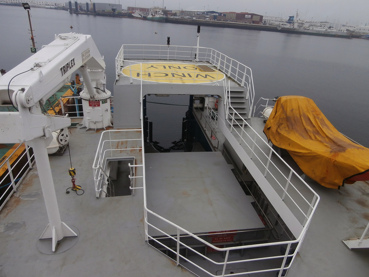
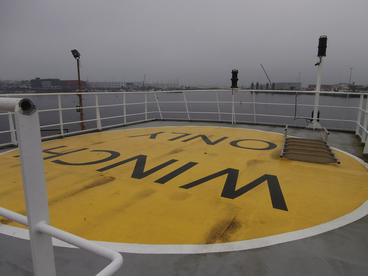
The existing aluminium heli-winching platform will be removed, and the steel deck will be continued towards the stern, as shown on the General Arrangement drawing.
A small closed deck-house will be built on port side only, to accommodate the CO2 cylinders and related devices. A hatch will give way to transfer the fishing gear from deck-4 to deck-3.
In general, handrails, stairs, aft navigation lights, etc., of that area, will be arranged as shown on the GA drawing.
On deck-3, will be removed the stern door, the cradle for the former work boat and its pneumatic launching and recovering system. The aft ramp will be eliminated together with its hydraulic cylinders, as well as the coamings and the hatches above the existing aft hold. The gap on deck will be closed and flushed up to the stern. Some new bulkheads will be made to surround the aft working area. The resulting space will accommodate the fishing gear setting area, the line arranger and other spaces as per the GA drawing.
The existing CO2 room, cold-provision machinery, paint locker and bosun’s workshop will be reworked as shown on the GA drawing.
On deck-2, the existing hydraulic lifting table will be eliminated. The workshop will be converted into a storage room for frozen bait, and the rest of spaces will be reorganised.
The space gained to the aft ramp and devices, and to the lifting table will be used to accommodate new refrigeration machinery, and those ancillaries that must be relocated somewhere. These equips are currently located forward, but that area has to be retrofitted as well.
The engine room will be mostly kept as it is. The door to access the workshop (frame #35) and the other one located forward to the auxiliary machinery room (frame #63), will be closed with steel plates, so the access to the E/R will be possible through the current stairs from aft deck, and the emergency exit forward.
Under deck-2, the aft ballast tank will be reworked to be a fuel tank, and some void spaces will be converted into fuel tank(s), as long as this were approved on the retrofit project.
Forebody
On the fore part of the ship, the aux. machinery room of deck-2 will be decommissioned. This space and the store forward of frame #83, will be emptied and reworked to accommodate the fish hold. The space below deck-2 will be redistributed into fuel tanks, as exposed before.
Deck-3 forward will provide the space needed for the hauling machinery and the wet fish processing. Besides that, the store room on top of the fore peak will accommodate the forward hydraulic power pack.
Deck house & Superstructures
The bridge will be redesigned as shown on the GA drawing. Most of the console desks will be the same, but it will be installed a new skipper’s chair on starboard together with the necessary desk(s) to accommodate electronics for fishing tasks, CCTV screens, etc. One bridge window on starboard will be replaced by a larger one, extending from top to bottom, for an improved visibility over the hauling area.
The accommodation superstructure on deck-4, will be partially reworked to accommodate the freezing tunnels as it is shown on the GA drawing. That cabins on deck-3 will be refitted to accommodate 4 people each, on two-tier bunker beds. A new emergency exit will be built around frame #68, as the current exit will be cancelled because it’s overlapping with the freezers above. Carpentry and furniture of the updated crew’s quarters will harmonize with the style of the existing items.
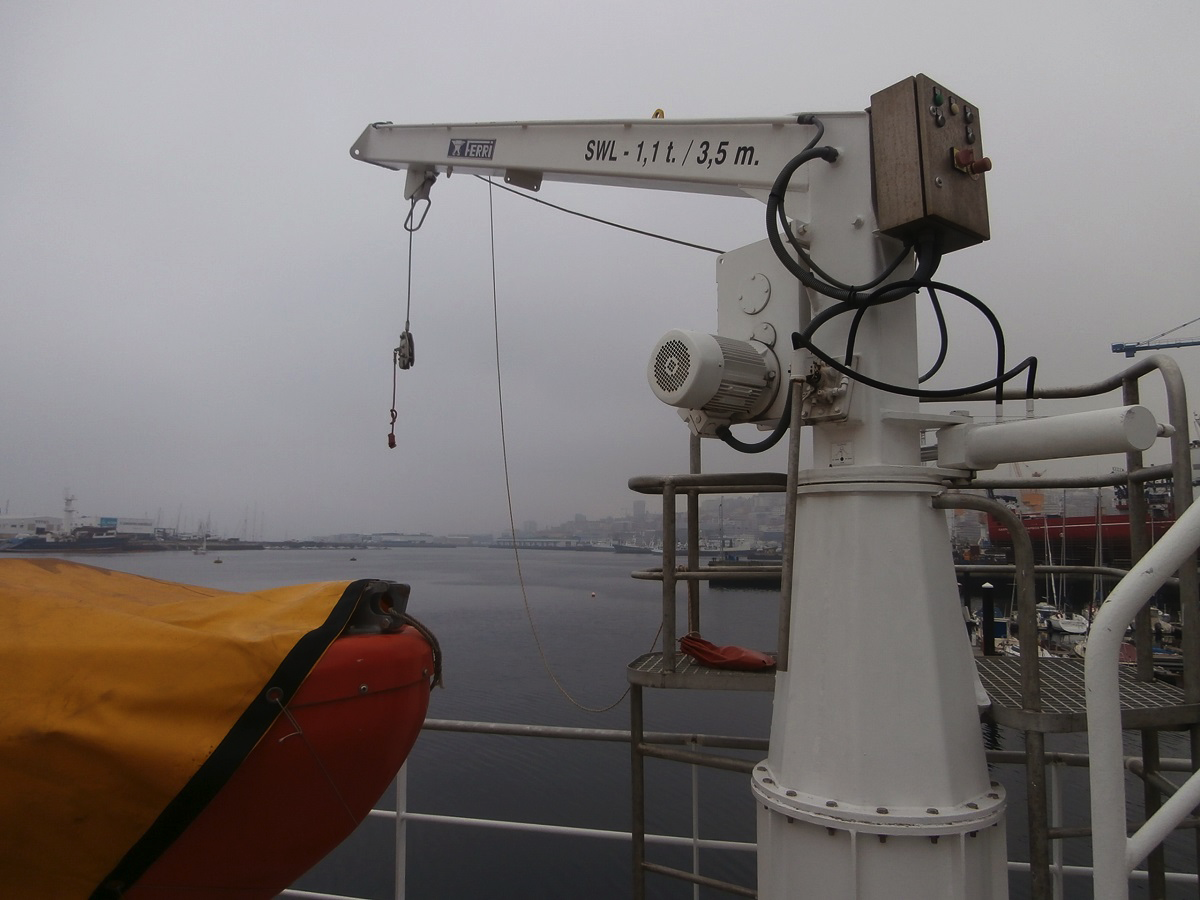
Cargo Lifting
The existing crane will be recommissioned and the final configuration of the cargo gear will be as follows.
Refrigeration Machinery
The main purpose of the refrigeration plant is to get ULT freezing and storage of tuna fish.
Refrigeration Systems for Catch Processing
All this machinery will be supplied by the ship owner and installed by the shipyard.
The ship owner will provide also, all the technical information and supplies needed for the correct installation, setting-up and commissioning of the refrigerating plant.
The shipyard will provide man power for the mechanical installation, pipe-fitting and electrical connection with the switchboards that would come with the machinery.
The ship owner will senD one (or more) commissioning engineers, included on their scope of supply, to check the installation progress and to perform start-up, tests and trials. The shipyard will provide worker(s) to help on that process.
The foreseen space reserved to accommodate the refrigeration machinery is that allocation depicted on the GA drawing.
Frozen Bait Storage and Cold-Provision System
The current refrigeration machinery for the cold-storage provision, will be updated and the compressors’ capacity extended, with new units to provide service to the bait storage to be installed into the former workshop room (Deck-2 port side). The design temperature for this, will be -18ºC. The room and its hatch will be insulated with polyurethane and lined with plywood and GRP.
Fish-Hold and Freezers Building-up and Insulation
The foreseen layout of freezers and fish-hold is that shown on the GA drawing. The fish-hold will be divided into six partitions for a better efficiency and conservation of the indoor temperature. There will be four freezer tunnels enclosed onto an insulated deck-house, attached forward of deck-4 accommodation spaces.
Insulation and Sheathing of the Fish-Hold
The fish hold will be designed for a temperature of -60ºC, and will be properly insulated. For this purpose, the following procedure will apply:
Bulkheads/sides, bottom and ceiling of the hold will be fitted with steel flat bars or profiles, welded to the ship’s structure. These profiles will act as supports to fix some 50x 50mm wood strips of red pine, forming grid squares of 600x600mm.
Rigid polyurethane foam with a density of 40kg/m² and injected above that framework will build-up a 200mm thick layer. The polyurethane will be smoothed and then shielded with WBP plywood (weather and boil proof), 15mm thick on the bottom and 10mm on the sides/bulkheads and ceiling.
The plywood will be finished with stratified glass-reinforced polyester (GRP) of a density of 300gr/m², applying two layers on the bottom and one layer on sides and ceiling. Finally, white topcoat will wrap the surfaces.
The bottom of the hold will be fitted with a floor-grid made of recycled plastic planks. That grid will comprise 120x35mm grooved planks, on top of 50x50mm strip sleepers and screwed or bolted altogether with stainless steel fittings.
Some vertical plastic battens, with a cross-section of 50x40mm will protect the inner part of the hold. These fenders will be 250mm evenly spaced, fixed with stainless steel screws and they will cover sides, bulkheads and pillars.
On the central corridor between port and starboard partitions, they will be installed six stainless steel door-frames and insulated swing doors, each leave of about 700x150x1900mm.
The cargo hatches will have an inner hatch, insulated with foam and wrapped with GRP and top coat as the rest of the insulation.
Insulation and Sheathing of the Freezer Tunnels
The freezing tunnels will be designed for a temperature of -65ºC, and will be properly insulated.
The doors of the tunnels will be swing or slide types, the most suitable for the case, with stainless steel door-frames and triple groove rubber gasket.
The building and sheathing system will be similar to that described for the hold above:
Rigid polyurethane foam with a density of 40kg/m² and injected above the structure or framework will build-up a 200mm thick layer. The polyurethane will be smoothed and then shielded with WBP plywood (weather and boil proof), 15mm thick on the bottom and 10mm on the sides/bulkheads and ceiling.
That plywood will be finished with stratified glass-reinforced polyester (GRP) of a density of 300gr/m², applying two layers on the bottom and one layer on sides and ceiling. Finally, white topcoat will wrap the surfaces.
The bulkheads, deck-floor and ceiling which enclose the freezer tunnels area will be insulated as above, and fitted with access doors, each leave of about 800x150x1800mm.
Machinery Tuning. Recommissioning
The current engines, machinery and ship’s systems will be re-commissioned in order to make sure everything is in order prior to set to sail.
The refrigeration plant will be feed from the AC 690V main switchboard, as the rest of big consumers on board, in order to match with the existing installation and to reduce the size of the feeding wires.
The current cooling system will be overhauled and the new refrigeration machinery will be connected to the sea water cooling system enabling the adequate flow rate for the condensing pumps. The ship owner has to submit enough information for the calculation of the new cooling arrangement to fit into the existing one.
Fish Finding and Navigation Electronics
The current electronic aids for navigation and communications on board will be updated. New fish-finding equipment will be installed as well. The list of electronics the retrofitted vessel will count on is that of the Annex 1. Bridge Equipment, as requested by the ship owner’s surveyor.
As a summary (*), navigation equipment includes at least:
• 2x Fish Finder
• Radar, X-band
• Radar, S-band
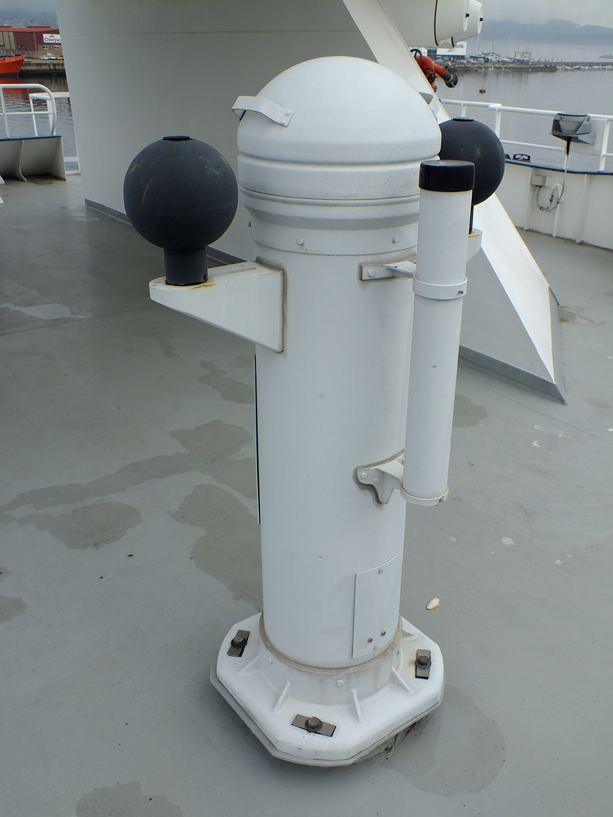
• Satellite Compass
• Gyro Compass
• Autopilot
• GPS Receiver
• GPS Receiver
• AIS
• Navigation Software
• GMDSS MF/HF Station
• Radio Station MF/HF
• GMDSS VHF
• Inmarsat C, GMDSS
• NAVTEX
• VHF/UHF Station
• Communications Scanner
• Portable VHF
• EPIRB
• SART
• Inmarsat FLEET
• Office Computers
(*) Check Annex 1 for models and details.
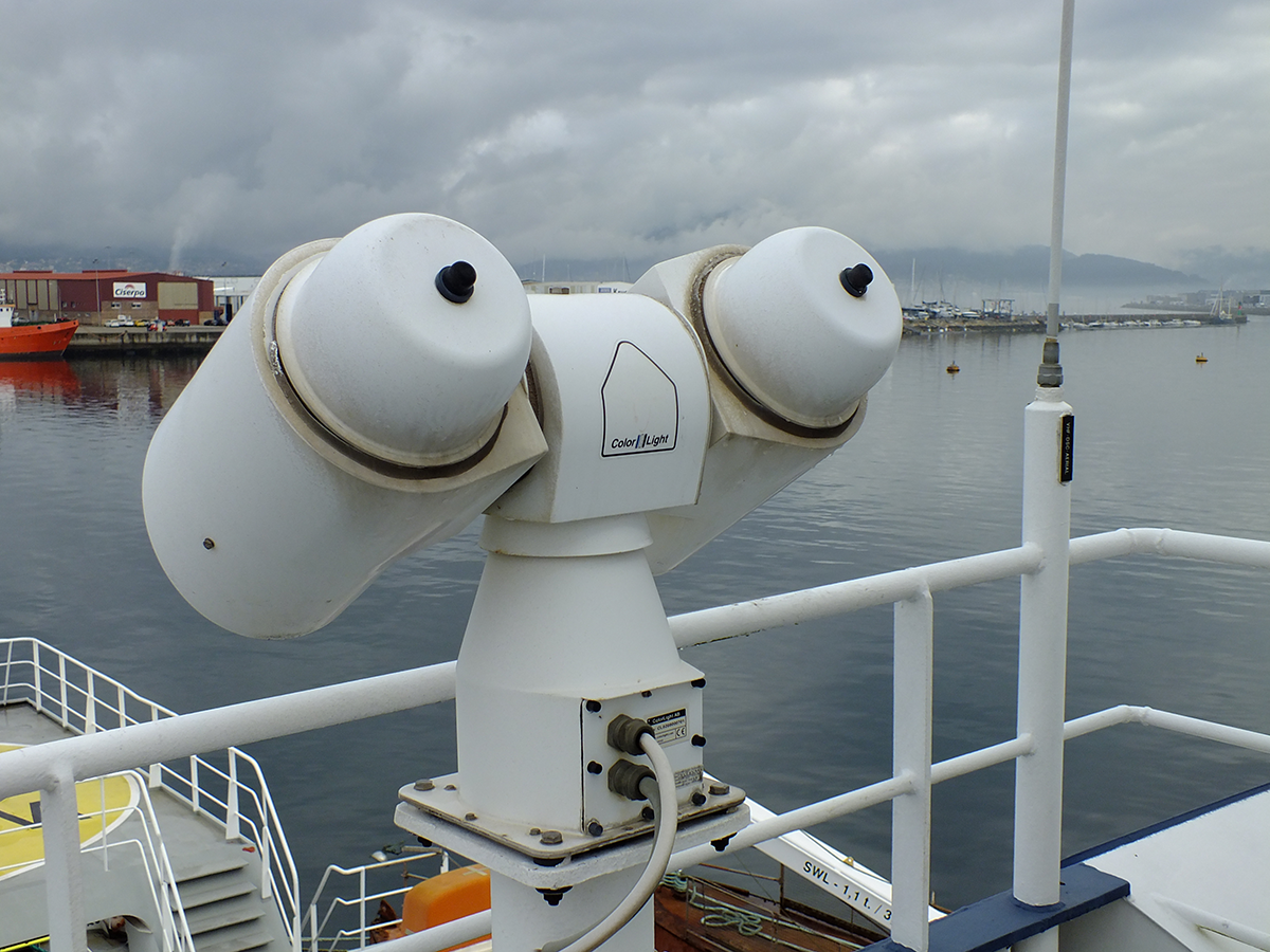
A comprehensive system of CCTV will be installed. It will expand the current installation and will encompass new cameras and further screens on the bridge. Those new cameras will cover the hauling and the setting working areas, for a better safety and to provide a suitable aid to the skipper to carry out the fishing manoeuvres.